This page is starting to accumulate a fair number of images and diagrams and may be slow to download via modem. My intent is to leave it as a single page for now. If you find it cumbersome to download please let me know and I will consider breaking it into separate pages.
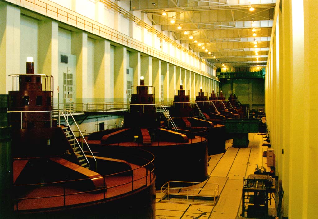
Grand Coulee Dam's hydroelectric generating facilities include four powerhouses (counting the pumping plant) with a total of 24 main generators, three station service generators and six pump/generators. These provide a combined generating capacity of 6480 megawatts. This makes Grand Coulee Dam the largest producer of hydroelectric power in the United States and the third largest such facility in the world.
| Generators at Grand Coulee Dam | ||||
|---|---|---|---|---|
| Location | Description | Number | Capacity (MW) | Total (MW) |
| Pumping Plant | Pump/Generator | 6 | 50 | 300 |
| Left Powerhouse | Station Service Generator | 3 | 10 | 30 |
| Main Generator | 9 | 125 | 1125 | |
| Right Powerhouse | Main Generator | 9 | 125 | 1125 |
| Third Powerhouse | Main Generator | 3 | 600 | 1800 |
| Main Generator | 3 | 700 | 2100 | |
| Totals | 33 | 6480 | ||
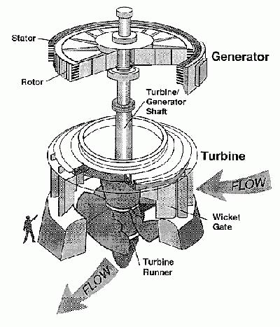
Above is a cutaway view of a turbine/generator assembly. As can be seen, water entering the turbine flows through a series of louvers, called wicket gates, which are aranged in a ring around the turbine inlet. The amount of water entering the turbine can be regulated by opening or closing the wicket gates as required. This allows the operators to keep the turbine turning at a constant speed even under widely varying electrical loads. Maintaining precise speed is important since it is the rate of rotation which determines the frequency of the electricity produced.
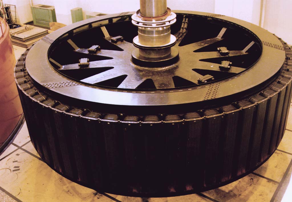
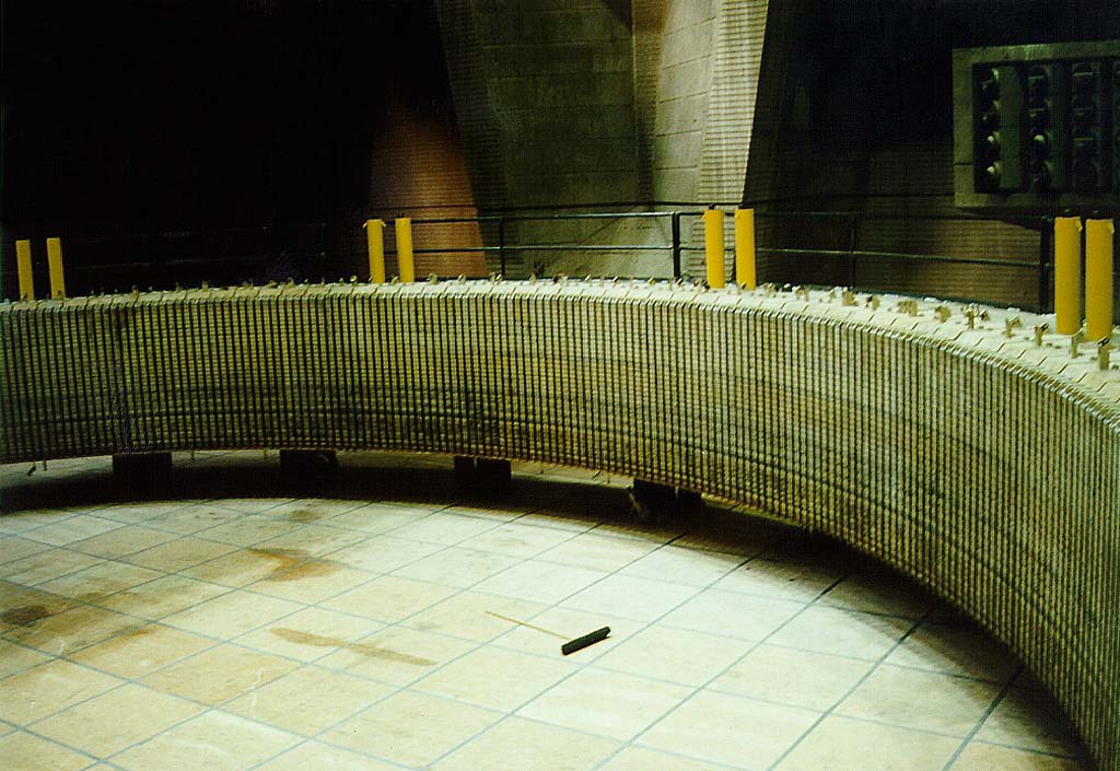
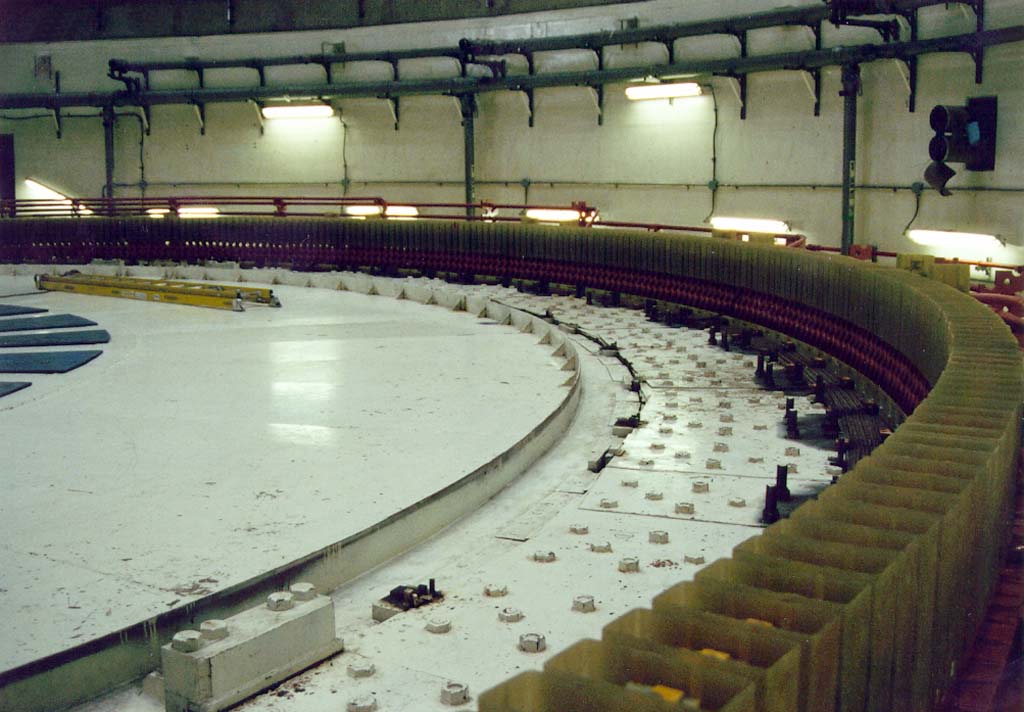
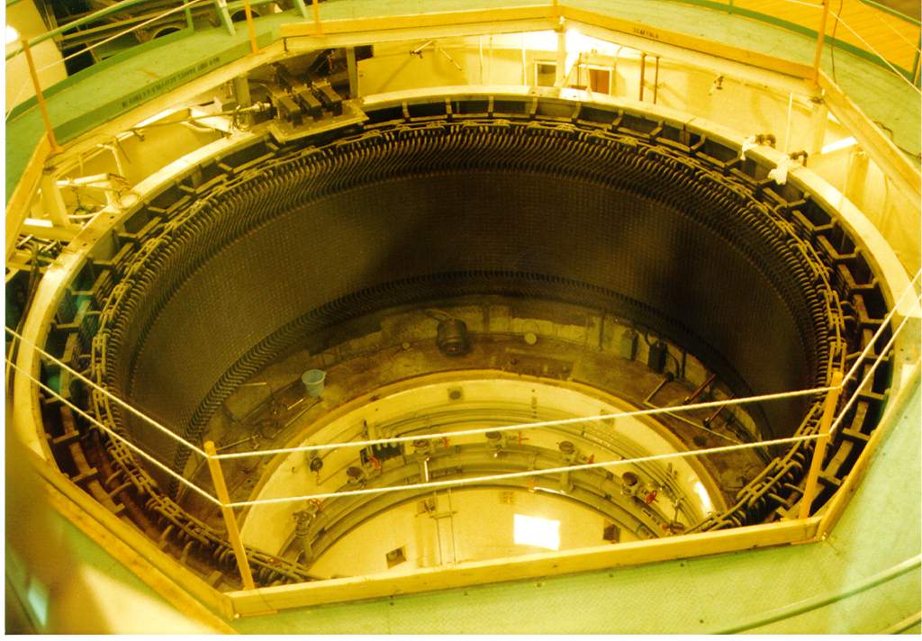
The turbine is coupled to an electric generator by a long shaft. The generator consists of a large, spinning "rotor" and a stationary "stator". The outer ring of the rotor is made up of a series of copper wound iron cells or "poles" each of which acts as an electromagnet. The stator is comprised of a series of vertically oriented copper coils nestled in the slots of an iron core. As the rotor spins its magnetic field induces a current in the stator's windings thereby generating electricity.
This is a cross section of the dam and right powerhouse. The major generator features are highlighted in blue.
From 250 feet below the surface of the reservoir water enters an 18 foot steel-lined tube called a penstock. From here it flows through the dam and into a spiral "scroll case". Directed through slots on the inner diameter of the scroll case the water falls through the turbine, causing it to spin. Finally the water enters the "draft tube". The larger diameter of this steel outlet tube slows the water before it exits the dam on the downstream side.
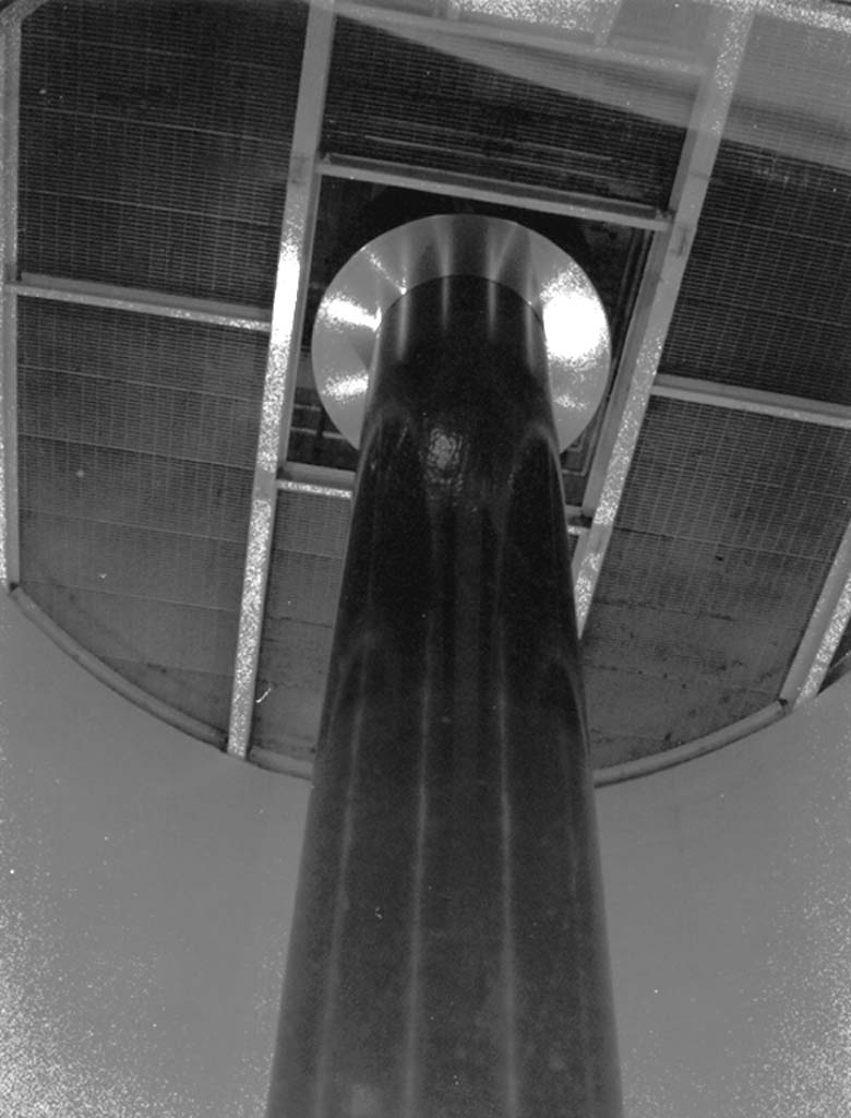
It is interesting to note the length of the shaft connecting the turbine to the generator. Long shafts were used to permit the generator to be well above the downstream water level. This design, popular in early hydroelectric projects, protects the generators from accidental flooding.
This is a cross section of the dam and third powerhouse. The major generator features are highlighted in blue.
This is a cross section of the wing dam and pumping plant. The major generator features are highlighted in blue. Note that this diagram is actually of a pump-only unit. The penstock, scroll case, draft tube, etc. of a pump/generator unit are quite similar.
| Created: | October 07, 1995 |
|---|---|
| Modified: | October 22, 1995 |